Showing posts with label Autocad. Show all posts

November 23, 2025

10 SolidWorks Exercises So Hard They Should Be Illegal (Free Download 2025)

10 SolidWorks Exercises So Hard They Should Be Illegal (Free Download 2025)

Stop scrolling if you think you’re “pretty good” at SolidWorks.Here are 10 parts that silently destroy 95 % of self-proclaimed “advanced” users:

  • One has a loft that changes cross-section three times and follows a 3D spline nobody can get right on the first try
  • One is a spoon that looks easy… until you try to make the thickness change from 6 mm to 1.5 mm without a single lump
  • One is a pipe with five 90° bends that must stay perfectly Ø42.4 × 2.6 mm all the way (good luck keeping the wall thickness)
  • One flange elbow will make you question your entire life choices when the section view doesn’t match

I modeled all of them in SolidWorks 2025, took screenshots of every critical step, and made fully dimensioned drawings that you can actually send to a workshop.Want to separate yourself from the crowd who can only do simple brackets?Download the pack (10 × .SLDPRT + 10 × .SLDDRW + PDF + all step-by-step images)
100 % free – no sign-up, no nonsense.Just click the big blue button at the end, unzip, and try not to rage-quit on part #4 Engineers who finished all 10 told me two things:

  1. “I thought I knew SolidWorks… I was wrong.”
  2. “My boss now thinks I’m a wizard.”

Your move.

Enjoy


Fully dimensioned 2D drawing of curved roller support bracket with section view A-A and isometric view


Final result – complete technical drawing: Main view, section A-A showing variable wall thickness (20 mm → 40 mm), all radii (R4, R30, R65, R50), overall dimensions and isometric view of the finished part.
SolidWorks drawing and 3D model of the bearing housing end cap with detailed dimensions

Bearing housing end cap (separate part): Start with a simple revolved boss/base from the provided sketch (Ø95 outer, Ø58 inner bore, Ø52 seat, Ø36 shaft bore, 8 mm wall thickness). Add 2.5 mm fillets on all edges and a 2×45° chamfer on the shaft exit.


SolidWorks 2D drawing and 3D model of the tensioning lever arm with M6 thread and mounting holes

Tensioning lever arm (separate part): Model using extruded base (50 mm height), extruded boss for the Ø60 mm rounded head, swept boss for the curved arm profile, M6 tapped hole + Ø12 counterbore, two Ø12 through holes and R10/R25 fillets. Final part is mirrored for left/right versions.

SolidWorks technical drawing and 3D model of the adjustable pipe clamp bracket with multiple holes and slots

Adjustable pipe clamp bracket: Base extrusion from rectangular sketch, two Ø20 circular bosses, Ø10 through holes, 18° angled slot (extruded cut), Ø30 central bore, R20 and R40 fillets on edges, plus small R1 chamfers. All features fully defined for easy modification.

SolidWorks 2D drawing and 3D model of the main curved roller support bracket with variable cross-section

Main curved roller support bracket (the hardest part): Created using Lofted Boss/Base between two sketches (30×20 mm rectangle → 40×40 mm rectangle) with a 3D spline guide curve (R30 + R65 + R50). Central Ø50 mm swept cut along the same path for the roller tube. Finished with R4 fillets on all outer edges and variable wall thickness shown in section A-A.

Dimensioned isometric view of a complex machined base block with angled pocket, multiple holes and curved slot in SolidWorks

Machined base block: Rectangular extruded base 200×100×90 mm, large central pocket with 45° and 150° angled faces (extruded cut), Ø12 through hole, curved slot created with swept cut, Ø25 counterbore + Ø12 hole on top face and several fillets/chamfers.

SolidWorks practice drawing 67 – curved block with multiple radii R20, R25, R15 and tapered ends


Curved sliding block (Modeling Practice 67): Extruded base 100×75×65 mm, large R20 and R25 rounded top surface using Swept Boss or Boundary Boss, tapered sides with 5 mm wall thickness, R15 fillet on front edge and 5 mm chamfers on bottom edges. Great exercise for advanced surfacing or multi-contour sweeps.

SolidWorks pipe bending exercise – multi-bend Ø42.4×2.6 tube with 5 segments, R60 bend radius and full BOM

Bent tubular frame (Ø42.4×2.6 mm pipe): Created using Sweep Boss/Base along 3D sketch containing five straight segments and four 90° bends with R60 radius. All bends fully defined in the 3D sketch, table lists exact segment lengths and bend angles – perfect exercise for 3D sketch + sweep + weldment structural members.

SolidWorks advanced spoon modeling exercise with variable thickness, multiple sections C-C, D-D, E-E and rendered view

Spoon with organic shape and variable thickness: Created using Lofted Boss/Base with five section profiles (from R10 circular bowl to thin 6 mm handle), guide curves for smooth transition, R40/R20/R10 fillets along the edges and variable wall thickness shown in sections. Excellent practice for complex lofts and surface blending.

SolidWorks flange elbow 90° with full section A-A, multiple diameters and R36 transition radius


 90° flanged elbow with complex internal flow path: Built using Revolved Boss/Base for both flanges, Lofted Boss/Base with two circular profiles and guide curves for the smooth R36 bend, Ø18 through bore, four Ø14 bolt holes on each flange (PCD 58 mm), R1 & R2 fillets and 5 mm wall thickness. Section A-A shows exact internal geometry.

BONUS

At the end. It would be ideal if you log in to the blog, comment and say what kind of drawings you want for practice.

As a reward for spending quality time reading this post, a reward follows. And that is the link to download all the drawings in this post in maximum resolution. Link to download the drawing.

You can find more drawings for practice on this post. Post.

On this channel you can find many free CAD modeling tutorials. Channel


January 6, 2023

Autocad Sheet metal

Sheet metal and Autocad. Sheet metal can be done very well and easily in Autocad.

Everyone who deals with mechanical engineering knows that it is very important to solve the development of sheet metal parts in an easy and accurate way. Autocad, a well-known system for CAD and 3D modeling, can perform this task.

Youtube free video tutorials

In the continuation of this post, you can watch 4 video tutorials that show tutorials for working with Autocad Sheet metal.

Autocad Sheet metal 1Autocad sheet metal 2

Autocad sheet metal 3Autocad Sheet metal 4

January 20, 2020

Models and drawings for exercise SolidWorks, 0041 - 0050

Slightly more complex models with workshop drawings.


The drawings have a view with dimensions and completed 3D models.


Enjoy


Solidworks model - 0041 Solidworks model - 0042
Solidworks model - 0043 Solidworks model - 0044

Solidworks model - 0045 Solidworks model - 0046

Solidworks model - 0047 Solidworks model - 0048


Models and drawings for exercise SolidWorks, 0031 - 040

Slightly more complex models with workshop drawings.

The drawings have a view with dimensions and completed 3D models.

Enjoy

Solidworks model - 0031 Solidworks model - 0032
Solidworks model - 0033 Solidworks model - 0034
Solidworks model - 0035 Solidworks model - 0036
Solidworks model - 0037 Solidworks model - 0037
Solidworks model - 0038 Solidworks model - 0039

January 19, 2020

Models and drawings for exercise SolidWorks, 0021 - 0030

Slightly more complex models with workshop drawings.

The drawings have a view with dimensions and completed 3D models.

Enjoy


September 24, 2019

Models and drawings for exercise SolidWorks, 0011 - 0020

FreeCAD, SolidWorks & AutoCAD Exercises – Mechanical Parts with Complete Technical Drawings (Download)

Welcome to a collection of fully dimensioned technical drawings ideal for practicing 3D modeling in FreeCAD, SolidWorks, AutoCAD and other CAD software. These exercises are perfect for beginners and intermediate users who want to improve skills in sketching, constraints, feature modeling, and technical documentation.

🛠 What You Can Learn From These Drawings

  • How to read and interpret professional mechanical drawings
  • Creating 2D sketches based on exact dimensions
  • Applying constraints and geometric relations
  • Using features like Extrude, Revolve, Fillet, Hole and Chamfer
  • Building complete 3D parts from standard workshop drawings

📐 Download Mechanical Drawings for Exercise

Below you will find a set of mechanical components with precise workshop dimensions. Each drawing can be directly used for modeling practice in:

  • FreeCAD Part Design / Sketcher
  • SolidWorks 3D Modeling
  • AutoCAD 2D to 3D workflow

All drawings include:

  • Orthographic views
  • Section views (where needed)
  • Complete dimensioning
  • Hole specifications and radii

📸 Technical Drawings Preview

Here are the drawings included in this exercise set:

Mechanical part drawing for FreeCAD and SolidWorks exercise


3D modeling exercise drawing AutoCAD FreeCAD SolidWorks


📥 Download Area

You can download the drawings directly from this post. They are ideal for classroom teaching, student practice or self-learning.

Click here to download:

Download Full Drawing Set (PDF/JPG)

💡 Recommended Tutorials

📌 Final Notes

Feel free to use these drawings for educational purposes, modeling practice or CAD learning. If you create 3D versions of these parts, share your results in the comments!

Happy modeling! 🚀

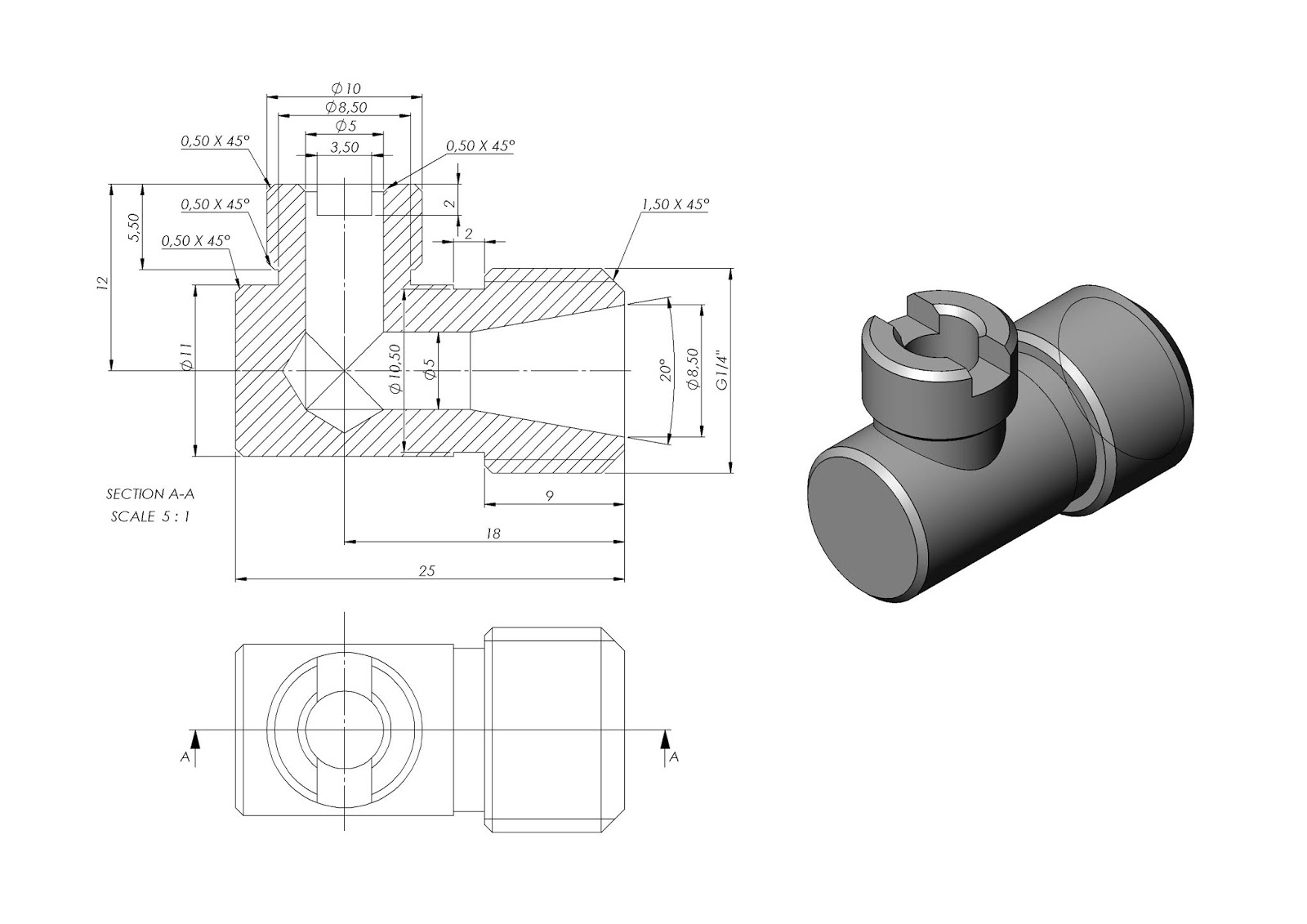
Here are more practical drawings to model your 3D models.

The drawings have a view with dimensions and completed 3D models.

Enjoy