Showing posts with label FreeCAD. Show all posts

January 25, 2026

10 Essential Mechanical Workshop Drawings: Master Engineering Designs for Your Projects!


Unlock the Power of Precision: 10 Must-See Mechanical Workshop Drawings

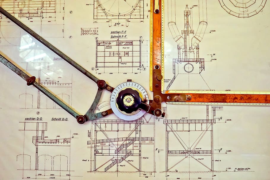
Professional mechanical engineering blueprint workshop drawing header

Precision engineering starts here – explore real workshop drawings!

Are you an aspiring engineer, CAD enthusiast, or workshop hobbyist looking for inspiration? These mechanical workshop drawings are goldmines for anyone diving into precision engineering! From intricate blueprints to practical designs, we've curated this collection to spark your creativity and help you tackle real-world projects. Whether you're using SolidWorks, AutoCAD, or just sketching by hand, these examples demonstrate key principles like tolerances, assemblies, and material specs.

Why these drawings rock:

  • Real-world applications: Perfect for machining, fabrication, and prototyping.
  • Beginner to pro: Simple enough for starters, detailed for experts.
  • Viral tip: Share your own versions in the comments below – let's build a community!

Scroll through, download ideas, and let us know which one is your favorite. If this inspires you, hit that share button to spread the engineering love! 🚀

Drawing 0021: Focus on gear assemblies – ideal for robotic projects. Tip: Check tolerances for smooth operation.

Drawing 0022: Sectional views for better understanding internals. Great for CNC milling.

Drawing 0023: Complex linkages – perfect for automation enthusiasts.

Drawing 0024: Focus on dimensions – essential for accurate builds.

Drawing 0025: Basic layout – start here if you're new to drafting.

Drawing 0026: Material notes included – key for durability.

Drawing 0027: Advanced tolerances – challenge yourself!

Drawing 0028: Step-by-step assembly – DIY friendly.

Drawing 0029: Custom parts design – innovate your workshop.

Drawing 0030: Series finale – combine with previous for full projects.

What do you think? Which drawing sparked an idea for you? Drop a comment, share this post, or tag a fellow engineer. Stay tuned for more SolidWorks tips! #MechanicalEngineering #CADDesign #WorkshopDrawings #EngineeringInspo

November 25, 2025

SolidWorks/FreeCAD Practice: 3D Modeling from Technical Drawings | Extreme SolidWorks

SolidWorks/FreeCAD Practice: 3D Modeling from Technical Drawings | Extreme SolidWorks

SolidWorks/FreeCAD Practice: Complete 3D Modeling from Workshop Drawings

📅 Estimated Time: 45-60 minutes per drawing
📐 Skill Level: Beginner to Intermediate
🎯 Goal: Develop technical drawing reading skills and 3D modeling proficiency

🎯 Introduction to the Exercise Series

In this comprehensive practice series, we'll use 10 workshop technical drawings with complete dimensions for 3D modeling practice in SolidWorks or FreeCAD. This exercise is perfect for:

  • 💡 Beginners wanting to practice technical drawing interpretation
  • 🔄 Experienced users looking to sharpen rapid modeling skills
  • 🎓 Students preparing for CAD examinations
  • 🏭 Engineers maintaining and developing design skills

📐 Workshop Drawings for Practice

Here are 10 technical drawings we'll use in this exercise series. Click on each image for larger view:

Drawing 0011: Bracket with Multiple Holes

Technical drawing 0011 - Bracket with multiple hole patterns

Features: Linear patterns, hole features, fillets
Difficulty: Easy

Drawing 0012: Complex Section View Part

Technical drawing 0012 - Complex part with section view A-A

Features: Section views, advanced dimensions
Difficulty: Medium

Drawing 0013: Bent Tube Profile

Technical drawing 0013 - Bent tube with multiple 90° angles

Features: Sweep features, bend radii
Difficulty: Easy

Drawing 0015: Angular Bracket

Technical drawing 0015 - Angular bracket with radius features

Features: Angular dimensions, R40 radius
Difficulty: Medium

Drawing 0016: Complex Assembly Part

Technical drawing 0016 - Complex mechanical part

Features: Multiple features, R8 fillets, complex geometry
Difficulty: Hard

Drawing 0017: Symmetrical Housing

Technical drawing 0017 - Symmetrical housing with pattern

Features: Symmetry, linear patterns, A20 annotation
Difficulty: Medium

Drawing 0018: Sectional Bearing Block

Technical drawing 0018 - Bearing block with section B-B

Features: Section views, R1 fillets, complex cuts
Difficulty: Hard

Drawing 0019: Simple Mounting Plate

Technical drawing 0019 - Simple mounting plate

Features: Basic extrusion, hole patterns
Difficulty: Easy

🔧 Step-by-Step Modeling Approach

1 Analyze the Technical Drawing

Before starting modeling, carefully analyze the drawing:

  • Identify main dimensions and tolerances
  • Study all views (front, top, side, isometric)
  • Note all holes, cuts, fillets, and chamfers
  • Understand material specifications
  • Identify datum references and critical features
💡 Pro Tip: Use different colors to highlight various features on the drawing before starting modeling. This helps in planning your feature tree.

2 Create Base Sketch in SolidWorks/FreeCAD

For SolidWorks Users:

1. File → New → Part
2. Select appropriate plane (Front, Top, Right)
3. Start 2D Sketch
4. Use Line, Circle, Rectangle tools
5. Add Smart Dimensions from drawing
6. Apply geometric relations (Horizontal, Vertical, Equal)
7. Exit Sketch → Extruded Boss/Base

For FreeCAD Users:

1. Create New → Part Design
2. Create Body → Create Sketch
3. Select appropriate plane (XY, XZ, YZ)
4. Use geometry creation tools
5. Add Constraints (dimensions)
6. Apply geometric constraints
7. Pad (extrude) the sketch

3 Add Secondary Features and Details

After base extrusion, add all secondary features:

Hole feature detail

Hole Features: Use Extruded Cut or Hole Wizard

Fillet feature detail

Fillets & Chamfers: Add edge treatments

4 Advanced Features and Final Touches

Add advanced features according to drawing specifications:

SolidWorks Advanced Features:
- Revolved Boss/Base for rotational parts
- Swept Boss/Base for complex paths
- Lofted Boss/Base for transitional shapes
- Mirror and Pattern features for symmetry
- Reference Geometry for complex alignments

🎯 Modeling Strategies by Difficulty

Difficulty Recommended Approach Time Estimate Key Challenges
Easy Single sketch + extrude + basic features 15-25 minutes Basic dimension interpretation
Medium Multiple sketches + features + patterns 30-45 minutes Feature order, relations management
Hard Complex sketches + advanced features + sections 45-60+ minutes Section views, complex geometry

⚡ Advanced Modeling Techniques

Parametric Modeling

Use parameters for easier modifications:

// SolidWorks Equations Example
"D1@Sketch1" = 100mm
"D2@Sketch1" = 50mm
"fillet_radius" = 5mm
"hole_pattern_count" = 4

Design Tables & Configurations (SolidWorks)

Create different variations of the part:

  • Configuration Manager → Add Configuration
  • Different dimensions for each configuration
  • Different materials and appearances
  • Suppress/unsuppress features

Assembly Techniques

For multi-part drawings:

1. Create individual parts
2. New Assembly → Insert Components
3. Apply Mates (Coincident, Concentric, Distance)
4. Check for interference
5. Create exploded views if needed

📊 Accuracy Verification Checklist

After completing each model, verify accuracy:

Parameter On Drawing In Model Verification Method
Overall Length As specified Measure Tool ✅ Correct / ❌ Incorrect
Hole Diameters As specified Measure Tool ✅ Correct / ❌ Incorrect
Fillet Radii R values Fillet Feature ✅ Correct / ❌ Incorrect
Material Volume Calculate Mass Properties ✅ Within Tolerance
Center of Mass N/A Mass Properties ✅ Logical Position

💡 Efficiency Tips for Professional Modeling

🔥 Pro Tip 1: Always use "Fully Defined" sketches in SolidWorks (sketch should be black, not blue) to avoid unexpected changes.
🔥 Pro Tip 2: Use geometric relations (Horizontal, Vertical, Equal, Parallel) before adding dimensions to reduce constraint complexity.
🔥 Pro Tip 3: Properly name features in the FeatureManager design tree for easier later modifications and team collaboration.
🔥 Pro Tip 4: Use Design Binder or Custom Properties to store drawing numbers, revisions, and other metadata directly in the part file.
⚠️ Common Mistake: Avoid over-defining sketches. If a sketch turns red, you have conflicting constraints or dimensions.

📁 Download Resources

Download all resources for this exercise series:

❓ Frequently Asked Questions

Q: Which SolidWorks version do I need for these exercises?
A: Any version from SolidWorks 2018 onwards. Some features might vary slightly.

Q: Can I use these drawings for commercial projects?
A: Yes, all drawings are free to use for personal and commercial purposes with attribution.

Q: How do I verify my model's accuracy?
A: Use Mass Properties tool in SolidWorks or FreeCAD to check volume and surface area against calculated values.

Q: What if my model has different mass properties than expected?
A: Check for: 1) Incorrect dimensions 2) Missing features 3) Extra features 4) Wrong material density settings.

Q: Should I model exactly as drawn or optimize the design?
A: For practice, model exactly as drawn. In real projects, always consider design optimization and manufacturability.

📈 Next Steps After Mastering These Exercises

After completing these practice drawings, we recommend progressing to:

  1. 💼 Assembly Drawings - how to assemble multiple parts
  2. 🎨 Photorealistic Rendering - creating professional visualizations
  3. 📋 Technical Documentation - creating workshop drawings from 3D models
  4. 🔄 Animation & Motion Study - moving parts and mechanisms
  5. 🏭 Manufacturing Preparation - CAM integration and DFM analysis
  6. 🌐 Collaborative Design - working with teams using PDM systems

🎉 Congratulations!

You've successfully completed a comprehensive series of 3D modeling exercises from workshop drawings. Continue practicing with the remaining drawings and challenge yourself with increasingly complex designs!

💬 Discussion & Community

Have questions or want to share your models? Leave a comment below! Join our community of CAD professionals and enthusiasts.

Tags: #SolidWorks #FreeCAD #3DModeling #CAD #Engineering #Tutorial #TechnicalDrawing #WorkshopDrawings #PracticeExercises #MechanicalDesign

Share your results: Post screenshots of your models on social media with #ExtremeSolidWorks


November 23, 2025

10 SolidWorks Exercises So Hard They Should Be Illegal (Free Download 2025)

10 SolidWorks Exercises So Hard They Should Be Illegal (Free Download 2025)

Stop scrolling if you think you’re “pretty good” at SolidWorks.Here are 10 parts that silently destroy 95 % of self-proclaimed “advanced” users:

  • One has a loft that changes cross-section three times and follows a 3D spline nobody can get right on the first try
  • One is a spoon that looks easy… until you try to make the thickness change from 6 mm to 1.5 mm without a single lump
  • One is a pipe with five 90° bends that must stay perfectly Ø42.4 × 2.6 mm all the way (good luck keeping the wall thickness)
  • One flange elbow will make you question your entire life choices when the section view doesn’t match

I modeled all of them in SolidWorks 2025, took screenshots of every critical step, and made fully dimensioned drawings that you can actually send to a workshop.Want to separate yourself from the crowd who can only do simple brackets?Download the pack (10 × .SLDPRT + 10 × .SLDDRW + PDF + all step-by-step images)
100 % free – no sign-up, no nonsense.Just click the big blue button at the end, unzip, and try not to rage-quit on part #4 Engineers who finished all 10 told me two things:

  1. “I thought I knew SolidWorks… I was wrong.”
  2. “My boss now thinks I’m a wizard.”

Your move.

Enjoy


Fully dimensioned 2D drawing of curved roller support bracket with section view A-A and isometric view


Final result – complete technical drawing: Main view, section A-A showing variable wall thickness (20 mm → 40 mm), all radii (R4, R30, R65, R50), overall dimensions and isometric view of the finished part.
SolidWorks drawing and 3D model of the bearing housing end cap with detailed dimensions

Bearing housing end cap (separate part): Start with a simple revolved boss/base from the provided sketch (Ø95 outer, Ø58 inner bore, Ø52 seat, Ø36 shaft bore, 8 mm wall thickness). Add 2.5 mm fillets on all edges and a 2×45° chamfer on the shaft exit.


SolidWorks 2D drawing and 3D model of the tensioning lever arm with M6 thread and mounting holes

Tensioning lever arm (separate part): Model using extruded base (50 mm height), extruded boss for the Ø60 mm rounded head, swept boss for the curved arm profile, M6 tapped hole + Ø12 counterbore, two Ø12 through holes and R10/R25 fillets. Final part is mirrored for left/right versions.

SolidWorks technical drawing and 3D model of the adjustable pipe clamp bracket with multiple holes and slots

Adjustable pipe clamp bracket: Base extrusion from rectangular sketch, two Ø20 circular bosses, Ø10 through holes, 18° angled slot (extruded cut), Ø30 central bore, R20 and R40 fillets on edges, plus small R1 chamfers. All features fully defined for easy modification.

SolidWorks 2D drawing and 3D model of the main curved roller support bracket with variable cross-section

Main curved roller support bracket (the hardest part): Created using Lofted Boss/Base between two sketches (30×20 mm rectangle → 40×40 mm rectangle) with a 3D spline guide curve (R30 + R65 + R50). Central Ø50 mm swept cut along the same path for the roller tube. Finished with R4 fillets on all outer edges and variable wall thickness shown in section A-A.

Dimensioned isometric view of a complex machined base block with angled pocket, multiple holes and curved slot in SolidWorks

Machined base block: Rectangular extruded base 200×100×90 mm, large central pocket with 45° and 150° angled faces (extruded cut), Ø12 through hole, curved slot created with swept cut, Ø25 counterbore + Ø12 hole on top face and several fillets/chamfers.

SolidWorks practice drawing 67 – curved block with multiple radii R20, R25, R15 and tapered ends


Curved sliding block (Modeling Practice 67): Extruded base 100×75×65 mm, large R20 and R25 rounded top surface using Swept Boss or Boundary Boss, tapered sides with 5 mm wall thickness, R15 fillet on front edge and 5 mm chamfers on bottom edges. Great exercise for advanced surfacing or multi-contour sweeps.

SolidWorks pipe bending exercise – multi-bend Ø42.4×2.6 tube with 5 segments, R60 bend radius and full BOM

Bent tubular frame (Ø42.4×2.6 mm pipe): Created using Sweep Boss/Base along 3D sketch containing five straight segments and four 90° bends with R60 radius. All bends fully defined in the 3D sketch, table lists exact segment lengths and bend angles – perfect exercise for 3D sketch + sweep + weldment structural members.

SolidWorks advanced spoon modeling exercise with variable thickness, multiple sections C-C, D-D, E-E and rendered view

Spoon with organic shape and variable thickness: Created using Lofted Boss/Base with five section profiles (from R10 circular bowl to thin 6 mm handle), guide curves for smooth transition, R40/R20/R10 fillets along the edges and variable wall thickness shown in sections. Excellent practice for complex lofts and surface blending.

SolidWorks flange elbow 90° with full section A-A, multiple diameters and R36 transition radius


 90° flanged elbow with complex internal flow path: Built using Revolved Boss/Base for both flanges, Lofted Boss/Base with two circular profiles and guide curves for the smooth R36 bend, Ø18 through bore, four Ø14 bolt holes on each flange (PCD 58 mm), R1 & R2 fillets and 5 mm wall thickness. Section A-A shows exact internal geometry.

BONUS

At the end. It would be ideal if you log in to the blog, comment and say what kind of drawings you want for practice.

As a reward for spending quality time reading this post, a reward follows. And that is the link to download all the drawings in this post in maximum resolution. Link to download the drawing.

You can find more drawings for practice on this post. Post.

On this channel you can find many free CAD modeling tutorials. Channel


August 2, 2024

Mastering FreeCAD: A Step-by-Step Guide to Modeling Scissors

Introduction

Are you eager to enhance your FreeCAD skills and tackle a fun, practical project? Look no further! In this comprehensive tutorial series, we guide you through the intricate process of modeling a pair of scissors in FreeCAD. Whether you're a beginner or an experienced user, these tutorials will help you master the art of 3D modeling. Let's dive in!


Part 1: Modeling the Metal Part

In the first video of our series, "FreeCAD - Tutorial - Scissors - Metal part - Modeling," we start with the fundamental component of our scissors - the metal part. This segment covers:

  • Basic Sketching Techniques: Learn how to create accurate 2D sketches that serve as the foundation for your 3D model.
  • Extrusion and Pad Tools: Discover how to transform your 2D sketches into 3D objects using the powerful extrusion and pad tools in FreeCAD.
  • Precision Editing: Fine-tune your model with precision editing tools to ensure every detail is perfect.

Watch the Metal Part Tutorial on YouTube


Key Takeaways:

  • Understanding the importance of a solid foundation in 3D modeling.
  • Mastering the use of basic tools in FreeCAD.
  • Developing the ability to create complex shapes from simple sketches.

Part 2: Crafting the Plastic Part

The second video, "FreeCAD - Tutorial - Scissors - Plastic part - Modeling," shifts focus to the plastic handles of the scissors. This part is essential for the ergonomics and usability of the scissors. Key points covered include:

  • Advanced Sketching: Dive deeper into sketching techniques to create the ergonomic shape of the handles.
  • Boolean Operations: Learn how to use Boolean operations to combine and subtract shapes, creating complex geometries.
  • Material Assignment: Assign materials and textures to different parts of your model to give it a realistic appearance.

Watch the Plastic Part Tutorial on YouTube


Key Takeaways:

  • Enhancing your sketching skills for more complex shapes.
  • Utilizing Boolean operations for intricate designs.
  • Understanding the importance of material properties in 3D modeling.

Part 3: Assembling the Scissors

In the final video, "FreeCAD - Tutorial - Scissors - Assembly - Modeling," we bring all the components together. This video covers:

  • Assembly Workbench: Introduction to the Assembly Workbench in FreeCAD, where you'll learn to assemble the individual parts.
  • Constraints and Joints: Learn how to apply constraints and joints to ensure that all parts fit together perfectly.
  • Simulation and Testing: Simulate the movement of the scissors to test the functionality of your design.

Watch the Assembly Tutorial on YouTube


Key Takeaways:

  • Gaining proficiency in the Assembly Workbench.
  • Understanding the importance of constraints and joints in assemblies.
  • Testing and validating the functionality of your model.

Conclusion

By following this comprehensive FreeCAD tutorial series, you'll gain the skills and confidence to tackle more complex projects. Each video builds upon the previous one, ensuring a smooth learning curve. Don't forget to subscribe to our YouTube channel for more tutorials and updates!

Call to Action:

  • Subscribe to Our Channel: Stay updated with the latest tutorials and tips by subscribing to our YouTube channel.
  • Join the Community: Share your progress and get feedback from other FreeCAD enthusiasts in our community forum.
  • Showcase Your Work: Tag us on social media with your finished projects for a chance to be featured!

Happy Modeling!


Author's Bio: Ivan Oblak is a passionate 3D modeling enthusiast and FreeCAD expert. With years of experience in the field, [Your Name] is dedicated to helping others unlock their creative potential through detailed tutorials and guides.

Social Media Links:

Related Posts:

Newsletter Signup: Stay updated with the latest tutorials and exclusive content by signing up for our newsletter here.


By integrating these elements, this blog post is designed to attract and engage readers, driving traffic to your YouTube tutorials and fostering a community of FreeCAD enthusiasts.

July 29, 2024

FreeCAD Tutorial: Revolution and Groove - Unleash Your Design Potential

FreeCAD Tutorial: Revolution and Groove - Unleash Your Design Potential

Welcome back to our FreeCAD tutorial series! Today, we're diving into two powerful features that will take your 3D modeling skills to the next level: Revolution and Groove. These tools are essential for creating complex, symmetrical shapes and intricate details. Whether you're a seasoned designer or just starting out, this step-by-step guide will help you master these features and create impressive models in no time.

What is FreeCAD?

For those new to FreeCAD, it’s an open-source parametric 3D CAD modeler. It's ideal for creating real-life objects of any size and is highly versatile, making it a favorite among engineers, designers, and hobbyists.

Let's Get Started: Understanding Revolution and Groove

Revolution allows you to create a 3D object by revolving a 2D shape around an axis. Think of it as spinning a shape around a central point to form a solid object. This is perfect for creating cylindrical or symmetrical parts like wheels, vases, or gears.

Groove, on the other hand, is used to cut out a groove or recess around a cylindrical part. It's like creating a trench or channel on the surface of a rounded object, which is essential for designs that require detailed cuts and indentations.

Step-by-Step Tutorial: Revolution

  1. Open FreeCAD and Create a New Document:

    • Start FreeCAD and create a new document. Go to File > New.
  2. Switch to the Part Design Workbench:

    • Change the workbench to Part Design from the dropdown menu.
  3. Create a Sketch:

    • Click on the Create Sketch button and select the plane where you want to draw (XY Plane is common).
  4. Draw Your 2D Shape:

    • Use the sketch tools to draw the profile of your object. For example, draw half of a vase or a gear tooth profile.
  5. Close the Sketch:

    • Once your shape is complete, click Close to exit the sketch.
  6. Apply the Revolution Tool:

    • Select your sketch from the model tree, then click on the Revolve button.
    • Set the axis around which you want to revolve your shape (usually the vertical or horizontal axis).
  7. Adjust Parameters:

    • You can adjust the angle of revolution (default is 360 degrees for a full revolution).
  8. Final Touches:

    • Click OK to complete the revolution. You now have a 3D object created from your 2D sketch!

Step-by-Step Tutorial: Groove

  1. Select the Revolved Object:

    • In the model tree, click on the object you created using the Revolution tool.
  2. Create a New Sketch:

    • Click Create Sketch and select the plane where you want to draw the groove (often perpendicular to the revolved object’s surface).
  3. Draw the Groove Profile:

    • Draw the profile of the groove you want to cut out. This could be a simple rectangle or a more complex shape.
  4. Close the Sketch:

    • Once your groove profile is complete, click Close to exit the sketch.
  5. Apply the Groove Tool:

    • Select your new sketch, then click on the Groove button.
    • Set the axis around which the groove will be cut (usually the axis of the revolved object).
  6. Adjust Parameters:

    • You can set the angle of the groove cut (default is 360 degrees for a complete groove around the object).
  7. Finalize Your Design:

    • Click OK to create the groove. You should now see a cut or trench around your object.

Tips for Success

  • Precision is Key: Ensure your sketches are precise for best results.
  • Experiment: Don’t be afraid to experiment with different shapes and parameters.
  • Save Often: Save your work frequently to avoid losing progress.

Watch the Tutorial Video

For a more detailed walkthrough, check out my tutorial video: FreeCAD - Tutorial - Revolution - Groove. In this video, I cover all the steps mentioned above and provide additional tips and tricks to help you get the most out of these features.


Conclusion

Congratulations! You've now mastered the basics of the Revolution and Groove tools in FreeCAD. These features are incredibly powerful and can be used to create a wide range of complex designs. Keep practicing, and you'll soon be creating professional-quality 3D models with ease.

Stay tuned for more FreeCAD tutorials, and don't forget to share your creations with us. Happy designing!


Feel free to make any adjustments or let me know if there's anything else you'd like to add!

July 18, 2024

FreeCad - Sheet metal - Tutorial - Modeling - Technical drawings

Introduction

FreeCad is an excellent CAD tool for working with thin sheet metal parts. It is excellent both for modeling parts and for developing the surface of those parts from thin sheets. In the following post, I will present excellent tutorials for those activities.

FreeCad - Sheet metal - Tutorial - Modeling

This video tutorial shows everything you need to model a sheet metal part.

Technical drawing

The first thing you need is a clearly defined technical drawing.

Technical drawing of thin sheet metal parts

Technical drawing of thin sheet metal parts

Software - FreeCad

Second and most important, you need 3d CAD software. FreeCad is freeware. You can download the program at the following link.


Learning to work with the Freecad software package

You can find a lot of material on the Internet and YouTube to easily learn how to work with this program.

The procedure of following the tutorial and learning the operation of Freecad

  1. Download the technical drawing from this post.
  2. Study the drawing carefully
  3. Start the Youtube link of this video tutorial
  4. Watch the video as many times as you like until you understand everything.
  5. Open the technical drawing and start FreeCad.
  6. Follow the procedure shown in the video tutorial.

Video tutorial

FreeCad, a video tutorial for working with a thin sheet metal part.


August 23, 2023

Solidworks as an ideal tool for any engineer

The software tool that every engineer must have is Solidworks. 

Solidworks as an ideal tool for any engineer


SolidWorks is the ideal software tool for any engineer. Solidworks is a CAD/CAM/CAE package that offers tools and functions to design, manufacture, and analyze product models.


Solidworks is a great choice for engineers who want to work in the field of computer aided design (CAD) or computer aided manufacturing (CAM). The program combines all these aspects together into one package, giving users the ability to create accurate designs, manufacture parts and assemblies, and analyze performance.


The software's functionality makes it one of the most popular CAD/CAM/CAE packages available today. It is suitable for both small and large companies alike as it can be used by anyone regardless of experience level or budget.


SolidWorks also has an excellent job sharing feature that allows users to share their files with other people who are using the same software on their computers so that they can collaborate on projects together without having to use email or other methods of communication.


Solidworks also offers all sorts of consultants who can help you with problems that may arise during your design process such as using different materials or dimensions for your parts, which will save you time and money on each project

January 26, 2023

Sheet metal drawings 1 - 14


Explanation

In your daily work, you come into contact with sheet metal parts. In order to make such parts, you need to have a developed surface and shape of those parts. Whether you are going to work in Solidworks or Freecad (programs that have tools for that) or some other specialized software, you must reach the level for quality work in 3d modeling. In this post, I provide you with 14 examples of metal parts for embroidery. There are easy parts and also medium complex ones. If you can't model the part, leave a comment with a contact email. Clarify what the problem is in the comment.