Showing posts with label Solidworks. Show all posts

January 25, 2026

10 Essential Mechanical Workshop Drawings: Master Engineering Designs for Your Projects!


Unlock the Power of Precision: 10 Must-See Mechanical Workshop Drawings

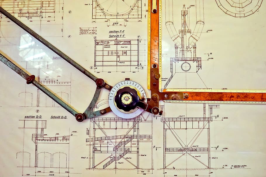
Professional mechanical engineering blueprint workshop drawing header

Precision engineering starts here – explore real workshop drawings!

Are you an aspiring engineer, CAD enthusiast, or workshop hobbyist looking for inspiration? These mechanical workshop drawings are goldmines for anyone diving into precision engineering! From intricate blueprints to practical designs, we've curated this collection to spark your creativity and help you tackle real-world projects. Whether you're using SolidWorks, AutoCAD, or just sketching by hand, these examples demonstrate key principles like tolerances, assemblies, and material specs.

Why these drawings rock:

  • Real-world applications: Perfect for machining, fabrication, and prototyping.
  • Beginner to pro: Simple enough for starters, detailed for experts.
  • Viral tip: Share your own versions in the comments below – let's build a community!

Scroll through, download ideas, and let us know which one is your favorite. If this inspires you, hit that share button to spread the engineering love! 🚀

Drawing 0021: Focus on gear assemblies – ideal for robotic projects. Tip: Check tolerances for smooth operation.

Drawing 0022: Sectional views for better understanding internals. Great for CNC milling.

Drawing 0023: Complex linkages – perfect for automation enthusiasts.

Drawing 0024: Focus on dimensions – essential for accurate builds.

Drawing 0025: Basic layout – start here if you're new to drafting.

Drawing 0026: Material notes included – key for durability.

Drawing 0027: Advanced tolerances – challenge yourself!

Drawing 0028: Step-by-step assembly – DIY friendly.

Drawing 0029: Custom parts design – innovate your workshop.

Drawing 0030: Series finale – combine with previous for full projects.

What do you think? Which drawing sparked an idea for you? Drop a comment, share this post, or tag a fellow engineer. Stay tuned for more SolidWorks tips! #MechanicalEngineering #CADDesign #WorkshopDrawings #EngineeringInspo

November 25, 2025

SolidWorks/FreeCAD Practice: 3D Modeling from Technical Drawings | Extreme SolidWorks

SolidWorks/FreeCAD Practice: 3D Modeling from Technical Drawings | Extreme SolidWorks

SolidWorks/FreeCAD Practice: Complete 3D Modeling from Workshop Drawings

📅 Estimated Time: 45-60 minutes per drawing
📐 Skill Level: Beginner to Intermediate
🎯 Goal: Develop technical drawing reading skills and 3D modeling proficiency

🎯 Introduction to the Exercise Series

In this comprehensive practice series, we'll use 10 workshop technical drawings with complete dimensions for 3D modeling practice in SolidWorks or FreeCAD. This exercise is perfect for:

  • 💡 Beginners wanting to practice technical drawing interpretation
  • 🔄 Experienced users looking to sharpen rapid modeling skills
  • 🎓 Students preparing for CAD examinations
  • 🏭 Engineers maintaining and developing design skills

📐 Workshop Drawings for Practice

Here are 10 technical drawings we'll use in this exercise series. Click on each image for larger view:

Drawing 0011: Bracket with Multiple Holes

Technical drawing 0011 - Bracket with multiple hole patterns

Features: Linear patterns, hole features, fillets
Difficulty: Easy

Drawing 0012: Complex Section View Part

Technical drawing 0012 - Complex part with section view A-A

Features: Section views, advanced dimensions
Difficulty: Medium

Drawing 0013: Bent Tube Profile

Technical drawing 0013 - Bent tube with multiple 90° angles

Features: Sweep features, bend radii
Difficulty: Easy

Drawing 0015: Angular Bracket

Technical drawing 0015 - Angular bracket with radius features

Features: Angular dimensions, R40 radius
Difficulty: Medium

Drawing 0016: Complex Assembly Part

Technical drawing 0016 - Complex mechanical part

Features: Multiple features, R8 fillets, complex geometry
Difficulty: Hard

Drawing 0017: Symmetrical Housing

Technical drawing 0017 - Symmetrical housing with pattern

Features: Symmetry, linear patterns, A20 annotation
Difficulty: Medium

Drawing 0018: Sectional Bearing Block

Technical drawing 0018 - Bearing block with section B-B

Features: Section views, R1 fillets, complex cuts
Difficulty: Hard

Drawing 0019: Simple Mounting Plate

Technical drawing 0019 - Simple mounting plate

Features: Basic extrusion, hole patterns
Difficulty: Easy

🔧 Step-by-Step Modeling Approach

1 Analyze the Technical Drawing

Before starting modeling, carefully analyze the drawing:

  • Identify main dimensions and tolerances
  • Study all views (front, top, side, isometric)
  • Note all holes, cuts, fillets, and chamfers
  • Understand material specifications
  • Identify datum references and critical features
💡 Pro Tip: Use different colors to highlight various features on the drawing before starting modeling. This helps in planning your feature tree.

2 Create Base Sketch in SolidWorks/FreeCAD

For SolidWorks Users:

1. File → New → Part
2. Select appropriate plane (Front, Top, Right)
3. Start 2D Sketch
4. Use Line, Circle, Rectangle tools
5. Add Smart Dimensions from drawing
6. Apply geometric relations (Horizontal, Vertical, Equal)
7. Exit Sketch → Extruded Boss/Base

For FreeCAD Users:

1. Create New → Part Design
2. Create Body → Create Sketch
3. Select appropriate plane (XY, XZ, YZ)
4. Use geometry creation tools
5. Add Constraints (dimensions)
6. Apply geometric constraints
7. Pad (extrude) the sketch

3 Add Secondary Features and Details

After base extrusion, add all secondary features:

Hole feature detail

Hole Features: Use Extruded Cut or Hole Wizard

Fillet feature detail

Fillets & Chamfers: Add edge treatments

4 Advanced Features and Final Touches

Add advanced features according to drawing specifications:

SolidWorks Advanced Features:
- Revolved Boss/Base for rotational parts
- Swept Boss/Base for complex paths
- Lofted Boss/Base for transitional shapes
- Mirror and Pattern features for symmetry
- Reference Geometry for complex alignments

🎯 Modeling Strategies by Difficulty

Difficulty Recommended Approach Time Estimate Key Challenges
Easy Single sketch + extrude + basic features 15-25 minutes Basic dimension interpretation
Medium Multiple sketches + features + patterns 30-45 minutes Feature order, relations management
Hard Complex sketches + advanced features + sections 45-60+ minutes Section views, complex geometry

⚡ Advanced Modeling Techniques

Parametric Modeling

Use parameters for easier modifications:

// SolidWorks Equations Example
"D1@Sketch1" = 100mm
"D2@Sketch1" = 50mm
"fillet_radius" = 5mm
"hole_pattern_count" = 4

Design Tables & Configurations (SolidWorks)

Create different variations of the part:

  • Configuration Manager → Add Configuration
  • Different dimensions for each configuration
  • Different materials and appearances
  • Suppress/unsuppress features

Assembly Techniques

For multi-part drawings:

1. Create individual parts
2. New Assembly → Insert Components
3. Apply Mates (Coincident, Concentric, Distance)
4. Check for interference
5. Create exploded views if needed

📊 Accuracy Verification Checklist

After completing each model, verify accuracy:

Parameter On Drawing In Model Verification Method
Overall Length As specified Measure Tool ✅ Correct / ❌ Incorrect
Hole Diameters As specified Measure Tool ✅ Correct / ❌ Incorrect
Fillet Radii R values Fillet Feature ✅ Correct / ❌ Incorrect
Material Volume Calculate Mass Properties ✅ Within Tolerance
Center of Mass N/A Mass Properties ✅ Logical Position

💡 Efficiency Tips for Professional Modeling

🔥 Pro Tip 1: Always use "Fully Defined" sketches in SolidWorks (sketch should be black, not blue) to avoid unexpected changes.
🔥 Pro Tip 2: Use geometric relations (Horizontal, Vertical, Equal, Parallel) before adding dimensions to reduce constraint complexity.
🔥 Pro Tip 3: Properly name features in the FeatureManager design tree for easier later modifications and team collaboration.
🔥 Pro Tip 4: Use Design Binder or Custom Properties to store drawing numbers, revisions, and other metadata directly in the part file.
⚠️ Common Mistake: Avoid over-defining sketches. If a sketch turns red, you have conflicting constraints or dimensions.

📁 Download Resources

Download all resources for this exercise series:

❓ Frequently Asked Questions

Q: Which SolidWorks version do I need for these exercises?
A: Any version from SolidWorks 2018 onwards. Some features might vary slightly.

Q: Can I use these drawings for commercial projects?
A: Yes, all drawings are free to use for personal and commercial purposes with attribution.

Q: How do I verify my model's accuracy?
A: Use Mass Properties tool in SolidWorks or FreeCAD to check volume and surface area against calculated values.

Q: What if my model has different mass properties than expected?
A: Check for: 1) Incorrect dimensions 2) Missing features 3) Extra features 4) Wrong material density settings.

Q: Should I model exactly as drawn or optimize the design?
A: For practice, model exactly as drawn. In real projects, always consider design optimization and manufacturability.

📈 Next Steps After Mastering These Exercises

After completing these practice drawings, we recommend progressing to:

  1. 💼 Assembly Drawings - how to assemble multiple parts
  2. 🎨 Photorealistic Rendering - creating professional visualizations
  3. 📋 Technical Documentation - creating workshop drawings from 3D models
  4. 🔄 Animation & Motion Study - moving parts and mechanisms
  5. 🏭 Manufacturing Preparation - CAM integration and DFM analysis
  6. 🌐 Collaborative Design - working with teams using PDM systems

🎉 Congratulations!

You've successfully completed a comprehensive series of 3D modeling exercises from workshop drawings. Continue practicing with the remaining drawings and challenge yourself with increasingly complex designs!

💬 Discussion & Community

Have questions or want to share your models? Leave a comment below! Join our community of CAD professionals and enthusiasts.

Tags: #SolidWorks #FreeCAD #3DModeling #CAD #Engineering #Tutorial #TechnicalDrawing #WorkshopDrawings #PracticeExercises #MechanicalDesign

Share your results: Post screenshots of your models on social media with #ExtremeSolidWorks


November 23, 2025

10 SolidWorks Exercises So Hard They Should Be Illegal (Free Download 2025)

10 SolidWorks Exercises So Hard They Should Be Illegal (Free Download 2025)

Stop scrolling if you think you’re “pretty good” at SolidWorks.Here are 10 parts that silently destroy 95 % of self-proclaimed “advanced” users:

  • One has a loft that changes cross-section three times and follows a 3D spline nobody can get right on the first try
  • One is a spoon that looks easy… until you try to make the thickness change from 6 mm to 1.5 mm without a single lump
  • One is a pipe with five 90° bends that must stay perfectly Ø42.4 × 2.6 mm all the way (good luck keeping the wall thickness)
  • One flange elbow will make you question your entire life choices when the section view doesn’t match

I modeled all of them in SolidWorks 2025, took screenshots of every critical step, and made fully dimensioned drawings that you can actually send to a workshop.Want to separate yourself from the crowd who can only do simple brackets?Download the pack (10 × .SLDPRT + 10 × .SLDDRW + PDF + all step-by-step images)
100 % free – no sign-up, no nonsense.Just click the big blue button at the end, unzip, and try not to rage-quit on part #4 Engineers who finished all 10 told me two things:

  1. “I thought I knew SolidWorks… I was wrong.”
  2. “My boss now thinks I’m a wizard.”

Your move.

Enjoy


Fully dimensioned 2D drawing of curved roller support bracket with section view A-A and isometric view


Final result – complete technical drawing: Main view, section A-A showing variable wall thickness (20 mm → 40 mm), all radii (R4, R30, R65, R50), overall dimensions and isometric view of the finished part.
SolidWorks drawing and 3D model of the bearing housing end cap with detailed dimensions

Bearing housing end cap (separate part): Start with a simple revolved boss/base from the provided sketch (Ø95 outer, Ø58 inner bore, Ø52 seat, Ø36 shaft bore, 8 mm wall thickness). Add 2.5 mm fillets on all edges and a 2×45° chamfer on the shaft exit.


SolidWorks 2D drawing and 3D model of the tensioning lever arm with M6 thread and mounting holes

Tensioning lever arm (separate part): Model using extruded base (50 mm height), extruded boss for the Ø60 mm rounded head, swept boss for the curved arm profile, M6 tapped hole + Ø12 counterbore, two Ø12 through holes and R10/R25 fillets. Final part is mirrored for left/right versions.

SolidWorks technical drawing and 3D model of the adjustable pipe clamp bracket with multiple holes and slots

Adjustable pipe clamp bracket: Base extrusion from rectangular sketch, two Ø20 circular bosses, Ø10 through holes, 18° angled slot (extruded cut), Ø30 central bore, R20 and R40 fillets on edges, plus small R1 chamfers. All features fully defined for easy modification.

SolidWorks 2D drawing and 3D model of the main curved roller support bracket with variable cross-section

Main curved roller support bracket (the hardest part): Created using Lofted Boss/Base between two sketches (30×20 mm rectangle → 40×40 mm rectangle) with a 3D spline guide curve (R30 + R65 + R50). Central Ø50 mm swept cut along the same path for the roller tube. Finished with R4 fillets on all outer edges and variable wall thickness shown in section A-A.

Dimensioned isometric view of a complex machined base block with angled pocket, multiple holes and curved slot in SolidWorks

Machined base block: Rectangular extruded base 200×100×90 mm, large central pocket with 45° and 150° angled faces (extruded cut), Ø12 through hole, curved slot created with swept cut, Ø25 counterbore + Ø12 hole on top face and several fillets/chamfers.

SolidWorks practice drawing 67 – curved block with multiple radii R20, R25, R15 and tapered ends


Curved sliding block (Modeling Practice 67): Extruded base 100×75×65 mm, large R20 and R25 rounded top surface using Swept Boss or Boundary Boss, tapered sides with 5 mm wall thickness, R15 fillet on front edge and 5 mm chamfers on bottom edges. Great exercise for advanced surfacing or multi-contour sweeps.

SolidWorks pipe bending exercise – multi-bend Ø42.4×2.6 tube with 5 segments, R60 bend radius and full BOM

Bent tubular frame (Ø42.4×2.6 mm pipe): Created using Sweep Boss/Base along 3D sketch containing five straight segments and four 90° bends with R60 radius. All bends fully defined in the 3D sketch, table lists exact segment lengths and bend angles – perfect exercise for 3D sketch + sweep + weldment structural members.

SolidWorks advanced spoon modeling exercise with variable thickness, multiple sections C-C, D-D, E-E and rendered view

Spoon with organic shape and variable thickness: Created using Lofted Boss/Base with five section profiles (from R10 circular bowl to thin 6 mm handle), guide curves for smooth transition, R40/R20/R10 fillets along the edges and variable wall thickness shown in sections. Excellent practice for complex lofts and surface blending.

SolidWorks flange elbow 90° with full section A-A, multiple diameters and R36 transition radius


 90° flanged elbow with complex internal flow path: Built using Revolved Boss/Base for both flanges, Lofted Boss/Base with two circular profiles and guide curves for the smooth R36 bend, Ø18 through bore, four Ø14 bolt holes on each flange (PCD 58 mm), R1 & R2 fillets and 5 mm wall thickness. Section A-A shows exact internal geometry.

BONUS

At the end. It would be ideal if you log in to the blog, comment and say what kind of drawings you want for practice.

As a reward for spending quality time reading this post, a reward follows. And that is the link to download all the drawings in this post in maximum resolution. Link to download the drawing.

You can find more drawings for practice on this post. Post.

On this channel you can find many free CAD modeling tutorials. Channel


January 3, 2024

Unleashing Creativity and Precision: A Comprehensive Guide to SolidWorks

Introduction:


In the dynamic realm of 3D modeling and design, SolidWorks stands as a stalwart, empowering engineers, designers, and innovators to bring their visions to life with precision and efficiency. This powerful computer-aided design (CAD) software has revolutionized the way we conceptualize and create products. In this comprehensive guide, we delve into the world of SolidWorks, exploring its features, benefits, and the myriad ways it fosters innovation.


Section 1: Understanding SolidWorks


SolidWorks is a parametric 3D CAD software developed by Dassault Systèmes. Its intuitive interface and robust tools make it a favorite among professionals across various industries. Let's explore some of its key features:


1. **Parametric Modeling:** SolidWorks employs a parametric approach, allowing users to create and modify designs by altering parameters. This feature facilitates easy experimentation and iteration during the design process.


2. **Assembly Modeling:** The software excels in creating intricate assemblies, enabling users to simulate the interaction between multiple components. This is invaluable for designing complex products and machinery.


3. **Sheet Metal Design:** SolidWorks provides specialized tools for sheet metal design, streamlining the process of creating components like enclosures and brackets. The software ensures accurate unfolding and precise manufacturing.


4. **Simulation and Analysis:** Engineers can perform virtual testing on their designs using SolidWorks Simulation. This feature aids in identifying potential issues and optimizing designs for performance and reliability.


Section 2: Advantages of SolidWorks


SolidWorks offers a plethora of advantages that contribute to its widespread adoption in the design and engineering community:


1. **User-Friendly Interface:** SolidWorks boasts an intuitive interface, making it accessible to both beginners and seasoned professionals. Its drag-and-drop functionality and contextual menus enhance usability.


2. **Extensive Library of Components:** The software includes an extensive library of standard components and fasteners, reducing design time and ensuring accuracy in assemblies.


3. **Collaboration and Integration:** SolidWorks facilitates collaboration among team members through features like cloud-based storage and integrated communication tools. This ensures seamless workflows and efficient project management.


4. **Parametric Intelligence:** The parametric nature of SolidWorks enables users to make changes at any stage of the design process without starting from scratch. This promotes flexibility and creativity.


Section 3: Industry Applications


SolidWorks finds applications across a multitude of industries, including:


1. **Automotive:** From concept design to manufacturing, SolidWorks aids in creating automotive components with precision and efficiency.


2. **Aerospace:** The software is instrumental in designing complex aerospace structures, ensuring compliance with stringent industry standards.


3. **Consumer Electronics:** SolidWorks facilitates the development of sleek and functional consumer electronics, from smartphones to smart home devices.


4. **Medical Devices:** In the medical field, SolidWorks helps in designing intricate and customized medical devices with a focus on precision and safety.


Conclusion:


SolidWorks stands as a cornerstone in the world of 3D modeling and design, offering a powerful suite of tools that cater to the diverse needs of professionals in various industries. Its user-friendly interface, robust features, and parametric intelligence make it an indispensable tool for those striving for innovation and excellence in their designs. Whether you're a seasoned engineer or a budding designer, SolidWorks is your gateway to unleashing creativity with unparalleled precision.


October 18, 2023

Enhancing Design Efficiency: Combining Excel Worksheets with SolidWorks

Introduction


In the world of engineering and product design, efficiency is paramount. Every little improvement in the design process can lead to significant time and cost savings. This blog post explores how you can leverage the power of Excel worksheets in conjunction with the SolidWorks program, a popular 3D CAD software, to streamline your design workflow. We'll provide practical examples and detailed elaboration of this integration to showcase its real-world applications.


## The Marriage of Excel and SolidWorks


Excel, a versatile spreadsheet tool, and SolidWorks, a robust 3D modeling software, might seem like an unlikely pair. However, when combined, they can offer a potent solution for design optimization and automation.


### Practical Examples


1. **Parametric Modeling**: Imagine you are designing a complex assembly with numerous components, and each component has multiple parameters like length, width, or weight. By linking an Excel worksheet to your SolidWorks model, you can update these parameters directly in Excel. This means that if a change is required, you don't have to individually modify each part within SolidWorks; the design updates automatically based on your Excel data.


2. **Bill of Materials (BOM) Management**: Managing a Bill of Materials is crucial in any engineering project. By integrating Excel with SolidWorks, you can create, update, and maintain BOMs more efficiently. Excel's powerful data management capabilities allow you to organize and customize your BOM, and any changes will be reflected in your SolidWorks model.


3. **Design Tables**: Design tables in SolidWorks are perfect for creating multiple configurations of a part or assembly. Excel can be used to manage these design tables, making it simple to create and modify various configurations. This is especially valuable for designs that have many variations or are highly customizable.


### Detailed Elaboration


Let's delve deeper into one of the practical examples mentioned above – Parametric Modeling.


**Parametric Modeling with Excel and SolidWorks**


1. **Linking Excel and SolidWorks**: Begin by creating an Excel worksheet with the relevant parameters for your design. You can define dimensions, tolerances, or any other variables needed. In SolidWorks, you can establish links to these cells by selecting the dimensions and linking them to specific Excel cells.


2. **Data-Driven Design**: Now, when you change a value in your Excel worksheet, it instantly reflects in your SolidWorks model. This feature is invaluable for design iterations, as it allows for quick and precise adjustments without the need to manually modify the design each time.


3. **Automated Calculations**: You can use Excel to perform calculations related to your design parameters. For instance, if you're designing a structural component and need to calculate stress based on changing loads, Excel can handle these calculations and update the SolidWorks model accordingly.


4. **Version Control**: Excel also enables you to maintain version control by keeping records of the design changes. This is vital for tracking design history and ensuring that you can always revert to a previous design if needed.


Conclusion


Integrating Excel worksheets with SolidWorks is a powerful method to enhance the efficiency of your design process. By automating repetitive tasks, such as parametric modeling and BOM management, you can save time and reduce the chances of errors. This synergy between two seemingly different software tools can result in a more streamlined and accurate design workflow, ultimately leading to better products and faster time-to-market.


In your engineering and design projects, consider harnessing the potential of Excel and SolidWorks to achieve a new level of productivity and precision. The marriage of these tools can transform the way you approach your design tasks, making your work not only more efficient but also more accurate and reliable.

August 23, 2023

How SolidWorks Can Revolutionize Engineering Work: The Ultimate Tool for Knowledge Accumulation, Load Calculation, and Cost Minimization


Introduction: SolidWorks - The Great Tool that Engineers Need for Everyday Work

SolidWorks, engineering software, CAD tool, design software, 3D modeling tool

How SolidWorks Can Revolutionize Engineering Work


The Power of SolidWorks in Knowledge Accumulation and Collaboration

knowledge accumulation in engineering, collaboration in SolidWorks, engineering design collaboration

  • Collaborative Design: Utilizing features like real-time collaboration and version control to enhance teamwork and knowledge sharing.

  • Design Documentation: Leveraging the capabilities of SolidWorks to create detailed documentation for future reference and knowledge preservation.

  • Centralized Design Repository: Managing design files efficiently to ensure easy access to accumulated knowledge throughout the organization.

Loading Calculation and Voltage State Analysis Made Easy with SolidWorks

SolidWorks load calculation, voltage state analysis, stress analysis in SolidWorks

  • Accurate Load Calculation: Using SolidWorks simulation tools to accurately calculate loads on different components or structures.

  • Voltage State Analysis: Analyzing the voltage distribution within an electrical system using SolidWorks Electrical module.

  • Error Identification: Detecting potential issues or weaknesses in designs by evaluating the stress levels on different parts.

Mimimizing Weight and Material Usage through Smart Design Practices in SolidWworks

Solidworks weight minimization, material optimization with SolidWorks, design optimization

  • Topology Optimization: Utilizing SolidWorks simulation capabilities to optimize designs and minimize weight while maintaining structural integrity.

  • Material Selection: Using SolidWorks' material libraries and analysis tools to identify the most suitable materials for specific applications.

  • Design Optimization: Applying SolidWorks' parametric modeling features to fine-tune designs and reduce unnecessary material usage.

Minimizing Cost with SolidWorks: An Engineer's Path to Efficient Design Processes

Solidworks cost minimization, cost-effective design with SolidWorks, design for manufacturing

  • CAD Integration: Seamlessly integrating SolidWorks designs with manufacturing processes to optimize production efficiency and reduce costs.

  • Detailed Simulation: Leveraging SolidWorks simulation tools to identify potential issues early in the design process, avoiding costly modifications later on.

  • Data-driven Decision Making: Utilizing data generated by SolidWorks simulations and analysis to make informed decisions that lead to cost savings in the long run.

Conclusion: Embrace the Power of Solidworks - Your Key to Revolutionary Engineering Work

Solidworks as an ideal tool for any engineer

The software tool that every engineer must have is Solidworks. 

Solidworks as an ideal tool for any engineer


SolidWorks is the ideal software tool for any engineer. Solidworks is a CAD/CAM/CAE package that offers tools and functions to design, manufacture, and analyze product models.


Solidworks is a great choice for engineers who want to work in the field of computer aided design (CAD) or computer aided manufacturing (CAM). The program combines all these aspects together into one package, giving users the ability to create accurate designs, manufacture parts and assemblies, and analyze performance.


The software's functionality makes it one of the most popular CAD/CAM/CAE packages available today. It is suitable for both small and large companies alike as it can be used by anyone regardless of experience level or budget.


SolidWorks also has an excellent job sharing feature that allows users to share their files with other people who are using the same software on their computers so that they can collaborate on projects together without having to use email or other methods of communication.


Solidworks also offers all sorts of consultants who can help you with problems that may arise during your design process such as using different materials or dimensions for your parts, which will save you time and money on each project

January 26, 2023

Sheet metal drawings 1 - 14


Explanation

In your daily work, you come into contact with sheet metal parts. In order to make such parts, you need to have a developed surface and shape of those parts. Whether you are going to work in Solidworks or Freecad (programs that have tools for that) or some other specialized software, you must reach the level for quality work in 3d modeling. In this post, I provide you with 14 examples of metal parts for embroidery. There are easy parts and also medium complex ones. If you can't model the part, leave a comment with a contact email. Clarify what the problem is in the comment.

December 12, 2022

SolidWorks Tutorial 2026 – Parametric Twisted Wire / Cable with Twist Along Path

SolidWorks Tutorial 2026 – Parametric Twisted Wire / Cable with Twist Along Path (Updated)

SolidWorks Tutorial 2026 – Parametric Twisted Wire / Cable with Twist Along Path (Updated & Redesigned)

Original Video Tutorial (2020) by Ivan Oblak:
Watch the step-by-step video demonstration here (Assembly context with equation table for parametric wire):

This is the **fully redesigned and updated 2026 text version** of the tutorial. It features cleaner steps, better global variables/equations setup, multi-strand options, and tips compatible with the latest SolidWorks releases. Use this as a companion guide or standalone reference.

Goal: Build a fully parametric single-wire or multi-strand twisted cable that updates instantly when you change diameter, length, twist count, or path – great for renders, animations, electrical mockups, or 3D printing.

Step 1 – Create the Path (3D Sketch or Helix)

  1. Insert → 3D Sketch.
  2. Draw the wire centerline using Spline (best for flexible/organic routing) or lines/arcs.
  3. Add tangent relations at ends if connecting to connectors.
  4. Fully define the sketch.
  5. Exit.
Perfect uniform twist path alternative: Insert → Curve → Helix/Spiral (faster for straight or cylindrical routing).

Step 2 – Create the Profile (2D Sketch)

  1. New 2D Sketch on Front Plane (or plane intersecting path start).
  2. Draw circle(s) for wire diameter (e.g. Ø1.8 mm).
  3. Add Pierce relation: circle center to path start point.
  4. Dimension diameter → link to global variable (Step 4).

Multi-strand version: Draw 2–19 small circles (circular pattern in sketch), space them realistically.

Step 3 – Swept Boss with Twist

  1. Features → Swept Boss/Base.
  2. Profile: select circle(s).
  3. Path: select 3D sketch or helix.
  4. Orientation/Twist Type: Twist Along Path.
  5. Define By: Revolutions → link to global variable.
  6. Optional: Tangent to Path for smooth ends.
  7. OK.

Step 4 – Parametrization with Equations

  1. Tools → Equations.
  2. Add global variables (examples):
"Wire_Dia"         = 1.80
"Twist_Revs"       = 24.0
"Path_Length"      = 450     (or link to path length dimension)
"Twist_per_meter"  = "Twist_Revs" / ("Path_Length"/1000)
  1. In Sweep: link revolutions to "Twist_Revs", diameter to "Wire_Dia".
  2. Save → change values in Equations → model rebuilds automatically.
Auto path length: In 3D sketch add Path Length Dimension → link "Path_Length" to it.

Step 5 – Enhancements for Realism

  • Multi-body: Sweep conductors first → then outer insulation (Thin Feature).
  • Appearances: Copper + rubber/plastic.
  • Fillet ends (0.3–0.8 mm).
  • High-twist rope: 7–19 strands + 40–80 revs.

Advanced Alternatives

  • Exact length calc: Measure path + equation.
  • Complex harness: Use SOLIDWORKS Routing / Electrical 3D.
  • Braided: Multiple helices + pattern.

Download free part from original video: Google Drive link

Happy modeling! Questions? Drop a comment. More tutorials coming soon.

Updated: January 2026 • Original video: November 2020

October 13, 2022

The ideal time has come for SolidWorks training

Dear friends, if anyone is interested in training for the SoliWorks software package, you are in the right place.

I am a mechanical engineer with extensive practical work experience. In my work I used SolidWorks, which is an indispensable tool for every engineer.

If someone wants me to give them online training, please contact me by email:

ivan.oblak@gmail.com.  

I also have a YouTube channel at the link: 

https://www.youtube.com/channel/UCKcSYKdBSLTA_fVlKxu6jhg

There you can find a lot of educational video tutorials, which can help you learn SolidWorks with ease.

Check out some of the tutorials.