Adsterra

Enhancing Design Efficiency: Combining Excel Worksheets with SolidWorks

Introduction


In the world of engineering and product design, efficiency is paramount. Every little improvement in the design process can lead to significant time and cost savings. This blog post explores how you can leverage the power of Excel worksheets in conjunction with the SolidWorks program, a popular 3D CAD software, to streamline your design workflow. We'll provide practical examples and detailed elaboration of this integration to showcase its real-world applications.


## The Marriage of Excel and SolidWorks


Excel, a versatile spreadsheet tool, and SolidWorks, a robust 3D modeling software, might seem like an unlikely pair. However, when combined, they can offer a potent solution for design optimization and automation.


### Practical Examples


1. **Parametric Modeling**: Imagine you are designing a complex assembly with numerous components, and each component has multiple parameters like length, width, or weight. By linking an Excel worksheet to your SolidWorks model, you can update these parameters directly in Excel. This means that if a change is required, you don't have to individually modify each part within SolidWorks; the design updates automatically based on your Excel data.


2. **Bill of Materials (BOM) Management**: Managing a Bill of Materials is crucial in any engineering project. By integrating Excel with SolidWorks, you can create, update, and maintain BOMs more efficiently. Excel's powerful data management capabilities allow you to organize and customize your BOM, and any changes will be reflected in your SolidWorks model.


3. **Design Tables**: Design tables in SolidWorks are perfect for creating multiple configurations of a part or assembly. Excel can be used to manage these design tables, making it simple to create and modify various configurations. This is especially valuable for designs that have many variations or are highly customizable.


### Detailed Elaboration


Let's delve deeper into one of the practical examples mentioned above – Parametric Modeling.


**Parametric Modeling with Excel and SolidWorks**


1. **Linking Excel and SolidWorks**: Begin by creating an Excel worksheet with the relevant parameters for your design. You can define dimensions, tolerances, or any other variables needed. In SolidWorks, you can establish links to these cells by selecting the dimensions and linking them to specific Excel cells.


2. **Data-Driven Design**: Now, when you change a value in your Excel worksheet, it instantly reflects in your SolidWorks model. This feature is invaluable for design iterations, as it allows for quick and precise adjustments without the need to manually modify the design each time.


3. **Automated Calculations**: You can use Excel to perform calculations related to your design parameters. For instance, if you're designing a structural component and need to calculate stress based on changing loads, Excel can handle these calculations and update the SolidWorks model accordingly.


4. **Version Control**: Excel also enables you to maintain version control by keeping records of the design changes. This is vital for tracking design history and ensuring that you can always revert to a previous design if needed.


Conclusion


Integrating Excel worksheets with SolidWorks is a powerful method to enhance the efficiency of your design process. By automating repetitive tasks, such as parametric modeling and BOM management, you can save time and reduce the chances of errors. This synergy between two seemingly different software tools can result in a more streamlined and accurate design workflow, ultimately leading to better products and faster time-to-market.


In your engineering and design projects, consider harnessing the potential of Excel and SolidWorks to achieve a new level of productivity and precision. The marriage of these tools can transform the way you approach your design tasks, making your work not only more efficient but also more accurate and reliable.

How SolidWorks Can Revolutionize Engineering Work: The Ultimate Tool for Knowledge Accumulation, Load Calculation, and Cost Minimization


Introduction: SolidWorks - The Great Tool that Engineers Need for Everyday Work

SolidWorks, engineering software, CAD tool, design software, 3D modeling tool

The Power of SolidWorks in Knowledge Accumulation and Collaboration

knowledge accumulation in engineering, collaboration in SolidWorks, engineering design collaboration

  • Collaborative Design: Utilizing features like real-time collaboration and version control to enhance teamwork and knowledge sharing.

  • Design Documentation: Leveraging the capabilities of SolidWorks to create detailed documentation for future reference and knowledge preservation.

  • Centralized Design Repository: Managing design files efficiently to ensure easy access to accumulated knowledge throughout the organization.

Loading Calculation and Voltage State Analysis Made Easy with SolidWorks

SolidWorks load calculation, voltage state analysis, stress analysis in SolidWorks

  • Accurate Load Calculation: Using SolidWorks simulation tools to accurately calculate loads on different components or structures.

  • Voltage State Analysis: Analyzing the voltage distribution within an electrical system using SolidWorks Electrical module.

  • Error Identification: Detecting potential issues or weaknesses in designs by evaluating the stress levels on different parts.

Mimimizing Weight and Material Usage through Smart Design Practices in SolidWworks

Solidworks weight minimization, material optimization with SolidWorks, design optimization

  • Topology Optimization: Utilizing SolidWorks simulation capabilities to optimize designs and minimize weight while maintaining structural integrity.

  • Material Selection: Using SolidWorks' material libraries and analysis tools to identify the most suitable materials for specific applications.

  • Design Optimization: Applying SolidWorks' parametric modeling features to fine-tune designs and reduce unnecessary material usage.

Minimizing Cost with SolidWorks: An Engineer's Path to Efficient Design Processes

Solidworks cost minimization, cost-effective design with SolidWorks, design for manufacturing

  • CAD Integration: Seamlessly integrating SolidWorks designs with manufacturing processes to optimize production efficiency and reduce costs.

  • Detailed Simulation: Leveraging SolidWorks simulation tools to identify potential issues early in the design process, avoiding costly modifications later on.

  • Data-driven Decision Making: Utilizing data generated by SolidWorks simulations and analysis to make informed decisions that lead to cost savings in the long run.

Conclusion: Embrace the Power of Solidworks - Your Key to Revolutionary Engineering Work

Solidworks as an ideal tool for any engineer

The software tool that every engineer must have is Solidworks. 


SolidWorks is the ideal software tool for any engineer. Solidworks is a CAD/CAM/CAE package that offers tools and functions to design, manufacture, and analyze product models.


Solidworks is a great choice for engineers who want to work in the field of computer aided design (CAD) or computer aided manufacturing (CAM). The program combines all these aspects together into one package, giving users the ability to create accurate designs, manufacture parts and assemblies, and analyze performance.


The software's functionality makes it one of the most popular CAD/CAM/CAE packages available today. It is suitable for both small and large companies alike as it can be used by anyone regardless of experience level or budget.


SolidWorks also has an excellent job sharing feature that allows users to share their files with other people who are using the same software on their computers so that they can collaborate on projects together without having to use email or other methods of communication.


Solidworks also offers all sorts of consultants who can help you with problems that may arise during your design process such as using different materials or dimensions for your parts, which will save you time and money on each project

Sheet metal drawings 1 - 14


Explanation

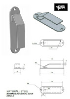
In your daily work, you come into contact with sheet metal parts. In order to make such parts, you need to have a developed surface and shape of those parts. Whether you are going to work in Solidworks or Freecad (programs that have tools for that) or some other specialized software, you must reach the level for quality work in 3d modeling. In this post, I provide you with 14 examples of metal parts for embroidery. There are easy parts and also medium complex ones. If you can't model the part, leave a comment with a contact email. Clarify what the problem is in the comment.

Autocad Sheet metal

Sheet metal and Autocad. Sheet metal can be done very well and easily in Autocad.

Everyone who deals with mechanical engineering knows that it is very important to solve the development of sheet metal parts in an easy and accurate way. Autocad, a well-known system for CAD and 3D modeling, can perform this task.

Youtube free video tutorials

In the continuation of this post, you can watch 4 video tutorials that show tutorials for working with Autocad Sheet metal.

Autocad Sheet metal 1Autocad sheet metal 2

Autocad sheet metal 3Autocad Sheet metal 4